Nihal and his classmates were excited for their school trip to the Bhakra Nangal Dam. There they would visit the hydroelectric power house where the force of falling water was used to generate electricity. They also looked forward to the free 13 kilometre- train ride from Nangal in Punjab to Bhakra in Himachal Pradesh, along the beautiful Sutlej river and through the Shivalik hills.Prior to the trip, Nihal and his classmates were given a group assignment to prepare a presentation on the uses of electricity. They began by looking around their houses, then their school, followed by their neighbourhood, their city, and fi nally they searched the internet. To their astonishment, their list kept growing. They decided to organise the uses under diff erent headings.
LightingHomes, offi ces, streets, markets, factories,_______________
TransportationTrain, bus, car, scooter, lift, escalator, _______________
Heating and CoolingFan, room heater, immersion rod, geyser, refrigerator, air conditioner, _____
CookingElectric kettle, mixer grinder, toaster, oven, microwave, _______________
EntertainmentTelevision, radio, _______________
CommunicationMobile phone, Internet, _______________
OthersWater pump, crane, computer, _______________
Can you help Nihal by adding some more uses to his lists? Also, suggest some other ways of grouping the uses of electricity.We use electricity all the time, so let us learn something more about electricity. You have learnt earlier that electricity is generated in multiple ways — by windmills, by using wind energy, by solar panels capturing the Sun’s energy, by falling water and by using natural gas or coal (in the chapter ‘Nature’s Treasures’ in the Grade 6 Science textbook Curiosity). The electric supply from these sources reaches our homes and factories via wires. For example, at home we plug in various devices to the electrical sockets in the wall. However, to learn about electricity, we will focus on a portable source of electricity that most of us may have used. Let us start with its use in a common device like a torchlight.Caution — The danger signs on electric poles and other appliances warn people that electricity can be dangerous if not carefully handled. Never ever perform experiments with power supply at your home or school. Even electricity from portable generators can be dangerous. Use only batteries or cells, like those in torchlights, wall clocks, radios, or remotes, for experiments with electricity.
3.1 A Torchlight
You might have used a torchlight, also called a torch or a flashlight.
Activity 3.1: Let us explore
• Take a torchlight similar to the one shown in Fig. 3.1.
• Observe it carefully. Do you notice a lamp? And a switch?
• Slide its switch and observe. Does the torch lamp glow?
• Now slide the switch back to its original position and observe the torch lamp.You might have noticed that in one position of the switch, the torch lamp glows and in the other position the lamp does not glow.
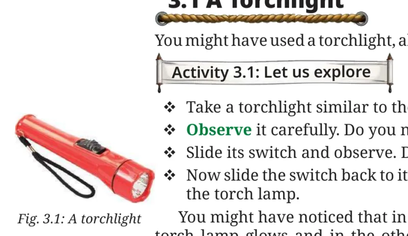
• Now, open the torchlight. What do you find inside?
Inside the torchlight, you may find two or more electric cells.
Why does the torch lamp glow in one position of its switch?
3.2 A Simple Electrical Circuit
To understand how a torch works, let us fi rst fi nd out about its components.
3.2.1 Electric cell
Activity 3.2: Let us observe
Negative terminal
Positive terminal
• Take an electric cell, turn it around and look at it carefully (Fig. 3.2). Do you notice a positive (+) sign and a negative (–) sign marked on the electric cell? Do you also notice that it has a small protruding metal cap on one side and a fl at metal disc on the other side?
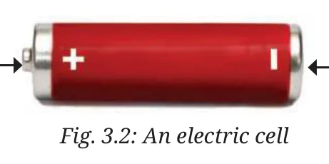
All electric cells have two terminals; one is called positive (+ ve) while the other is negative (– ve). The metal cap is the positiveterminal of the electric cell and the metal disc is the negativeterminal. The electric cell is a portable source of electrical energy.
3.2.2 Battery
In a torch, we generally use more than one cell. Are those placed in any particular order?
Activity 3.3: Let us experiment
• Take a torch which uses two cells. Open its cell compartment and take out the cells.
• Put the cells back in a diff erent order. Also, try reversing the direction of one cell. Then, slide the switch and check whether the lamp glows in each case.
• Check the order in which the cells were placed in the torch when the lamp glows.
The lamp glows when the cells are placed in the order as shown in Fig. 3.3. Notice how the terminals of the two cells are connected. The positive terminal of one cell is connected to the negative terminal of the next cell. Such a combination of two or more cells is called a battery.
(a)
(b)
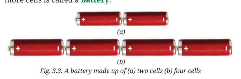
For many devices, we may need more than one cell. So, we connect two or more cells together as shown in Fig. 3.3. Connecting more than one cell provides energy to the circuit for a longer time and/or more energy.
FASCINATING FACTS
The term battery is also used for a single cell. We use the term battery even for the single cell that powers our mobile phones.
3.2.3 Electric lamp
Incandescent Lamp
Activity 3.4: Let us observe
For this activity, you will require a torchlight with an incandescent lamp (or light bulb). Many old torchlights still use such lamps. With your teacher’s help, confi rm that your torchlight uses an incandescent lamp. • Take the torch and examine its lamp. What do you see? Do you notice a thin wire fi xed in the middle of the glass bulb?
Glass bulb
Filament
Thick wire
Thick wire
Insulator (support)
Metal case (other terminal)
• Now, switch on the torch. Which part of the lamp glows?
Insulator
The thin wire inside the glass bulb of the lamp glows. The glowing thin wire is called the fi lament of the lamp. • Take out the lamp with the help of your teacher and inspect it from all sides. How is the fi lament fi xed?
Metal tip(one terminal)
(a)
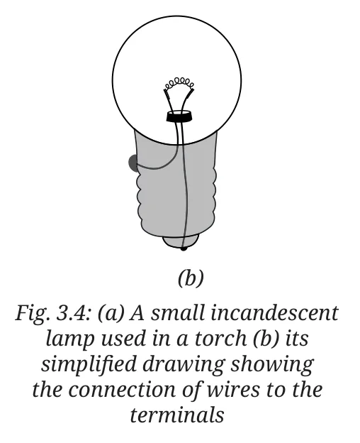
The fi lament is attached to two thicker wires that support it, as shown in Fig. 3.4a. One thick wire connects to the metal case at the lamp’s base, while the other connects to the metal tip at the centre of the base (Fig. 3.4b). These form the two terminals of the lamp, and are fi xed in a way that they do not touch each other. In such incandescent lamps, the fi lament gets hot and glows to produce light.
(b)
However, my torch has a diff erent kind of lamp. In fact, it cannot be taken out of the torch as it is fi xed in it.
LED Lamp
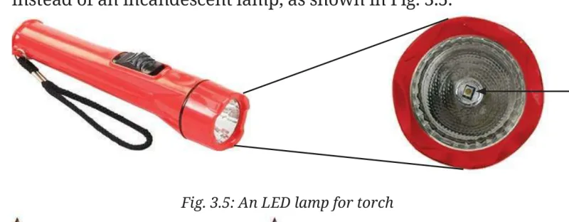
Many torches in use today have a Light Emitting Diode (LED) lamp, instead of an incandescent lamp, as shown in Fig. 3.5.
LED lamp
Activity 3.5: Let us observe
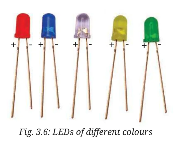
• Take an LED of any colour (Fig. 3.6) and observe. Do you see any fi lament inside it?
• Notice the length of two wires attached to the LED. Do you fi nd one of those longer than the other?
+- ++++----
Unlike incandescent lamps, LEDs do not have fi laments (Fig. 3.6). They also have two terminals, but one is positive (attached to a longer wire) and the other is negative (the shorter wire). A torch may use one or more LEDs, sometimes of diff erent shapes, in its lamp.After having learnt about the electric cell, battery, and electric lamps, we are now ready to make the torch lamp glow using an electric cell or battery.
3.2.4 Making an electric lamp glow using an electric cell or battery
Activity 3.6: Let us construct
• Take an electric cell, an incandescent lamp used in a torch, a cell holder, a lamp holder, and four lengths of electric wire.
• Remove about 1 cm of the plastic covering from both ends of each wire to expose the metal.
• Attach two wires to the two ends of the cell holder as shown in Fig. 3.7a.
Spring
(a)(b)(c)
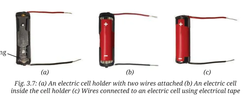
• Insert the cell in the holder such that its negative terminal is towards the spring side of the holder (Fig. 3.7b). In case a cell holder is not available, fi x the two wires to the cell using electrical tape (Fig. 3.7c).
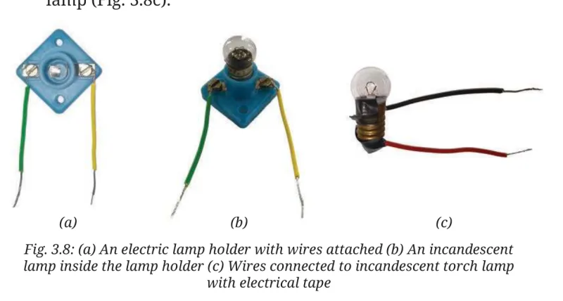
• Attach two wires to the screws of the lamp holder as shown in Fig. 3.8a. Fix the lamp in the holder by turning it around in the holder (Fig. 3.8b). In case a lamp holder is not available, use electrical tape to attach two wires to the two ends of the lamp (Fig. 3.8c).
(a)(c)
(b)
Now, we are ready to connect the cell to the lamp to make it glow. • We will conduct this activity in two parts — prediction and observation. Some of the ways in which the lamp and the cell can be connected are shown in Table 3.1.
• Predict, for each arrangement, if the lamp will glow or not and write your prediction in Table 3.1.
• Now, connect the lamp and the cell, and observe if the lamp glows or not. Note down your observation in Table 3.1. Also, for the lamps which glow, colour their glass bulbs yellow.
Note: The lamps are not shown glowing in any circuit
S.No.Arrangement of Cell and Lamp
PredictionObservation
1.
2.
3.
4.
5.
6.
The lamp glows in the arrangements at S.No. 1 and 6 and does not glow in the remaining arrangements. Now, carefully look at the arrangements in which the lamp glows. Compare these with those in which the lamp does not glow. Can you find the reason for the difference?
3.2.5 An electrical circuit
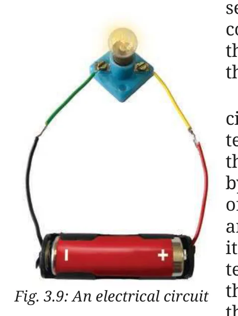
The lamp glows when one terminal of the lamp is connected to one terminal of the electric cell and the other terminal of the lamp to the other terminal of the cell as shown in Fig. 3.9. This setup forms an electrical circuit, which provides a complete path for electric current to flow through the lamp. The lamp glows only when current passes through the circuit.The direction of electric current in an electrical circuit is taken to be from the positive to the negative terminal of the electric cell. When the terminals of the lamp are connected with those of the electric cell by wires, the current passes through the filament of the incandescent lamp and makes it glow. With an incandescent lamp, it does not matter which of its terminals connects to the positive or negative terminal of the cell. The lamp will glow as long as the circuit is complete and current flows through the filament.
FASCINATING FACTS
Sometimes, an incandescent lamp does not glow even when connected to a cell. We say the lamp has ‘fused’ usually due to a broken filament. A broken filament stops the flow of current, preventing the lamp from glowing.
Let us now try to make an LED glow.
Activity 3.7: Let us experiment
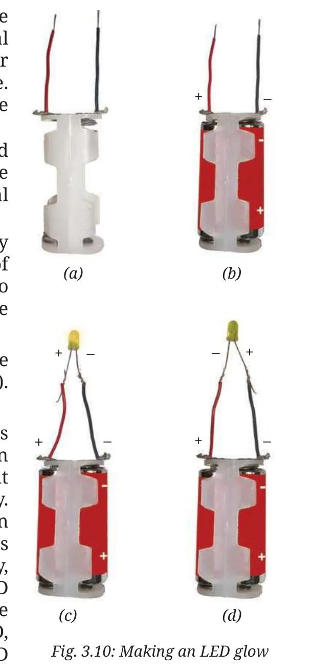
• Take two electric cells, an LED of any colour, a cell holder that can fit two cells (Fig. 3.10a), and two lengths of electric wire. • Remove about 1 cm of the plastic covering from both ends of each wire to expose the metal. • Connect the two wires to the cell holder as shown in Fig. 3.10a.
• Insert two cells in the holder, taking care that for each cell, its negative terminal is towards the spring side of the holder (Fig. 3.10b) and the battery is ready to use. How will you decide which is the positive terminal of this battery?The terminal of the holder which is connected to the positive terminal of one cell is positive and the one connected to the negative terminal of the other cell is the negative terminal. • Now, connect the free end of the battery positive terminal wire to the longer wire of LED, and the free end of the second wire to the shorter wire of LED (Fig. 3.10c). Does the LED glow?
+–
(a)
(b)
• Repeat the above step but interchange the wires connected to the LED (Fig. 3.10d). Does the LED glow again?
You would have observed that the LED glows in the fi rst case (Fig. 3.10c) and does not glow in the other (Fig. 3.10d). It is because the current can pass through the LED in one direction only. The current passes through the LED only when the positive terminal (longer wire) of the LED is connected to the positive terminal of the battery, and negative terminal (shorter wire) of the LED is connected to the negative terminal of the battery. When current passes through the LED, it glows. Always take care to connect an LED correctly in a circuit to make it glow.
(c)
(d)
Sometimes you may come across a device in which the cells are placed side by side. Then, how are the terminals of the cells connected?If you carefully look inside the battery compartment, you will usually see a thick wire or metal strip connecting the positive terminal of one cell to the negative terminal of the next. To help with proper placement, ‘+’ and ‘–’ symbols are typically printed inside.
ed
DIVEEEPER
IVE
side by side. Then, how are the terminals
EEPER
de
th
ou
or
po
to
th
pl
ar
3.2.6 Electric switch
How does a switch turn on or off the torchlight?
Let us first make a simple switch on our own.
Activity 3.8: Let us construct
• Collect two drawing pins, a safety pin (or a paper clip), two wires, and a small piece of cardboard.
• Insert a drawing pin through the ring of the safety pin and fix it to the cardboard piece, ensuring that the safety pin can rotate freely (Fig. 3.11a).
(a)
• Fix the second drawing pin to the cardboard piece so the free end of the safety pin can touch it (Fig. 3.11b).
(b)
• Connect a wire to each drawing pin — our switch is ready!
Let us now test our switch.
Activity 3.9: Let us test
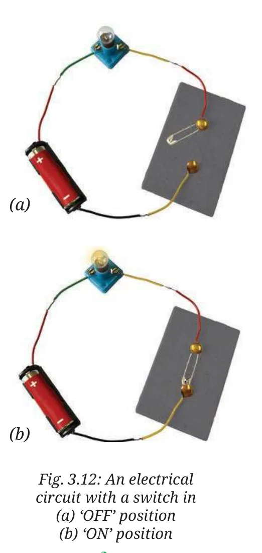
• Connect the electric cell, lamp, and switch as shown in Fig. 3.12a. Does the lamp glow?
• Rotate the free end of the safety pin till it touches the other drawing pin as shown in Fig. 3.12b. Does the lamp glow now?
When the safety pin touches both drawing pins, it closes the gap and completes the path, and allows the current to flow. We call this the ON position (Fig. 3.12b) where the circuit is closed and current flows from the cell’s positive to negative terminal making the lamp glow. When the safety pin does not touch the second drawing pin, the gap in the circuit prevents current flow, and the lamp does not glow. In this OFF position (Fig. 3.12a), we say that the circuit is open.Note that a switch can be placed anywhere in a circuit. A switch is a simple device that either completes or breaks a circuit. The switches used for lights and other devices at home work the same way, though they are designed differently.
(a)
(b)
3.3 Circuit Diagrams
Can we represent the circuits in a simpler manner?
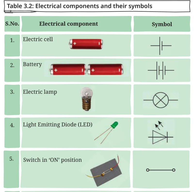
The various components of an electrical circuit can be represented by symbols shown in Table 3.2.
S.No.Electrical component
Symbol
Electric cell
1.
Battery
2.
3.
Electric lamp
Light Emitting Diode (LED)
D)
4.
5.Switch in ‘ON’ position
6.Switch in ‘OFF’ position
Wire7.
In the symbol for an electric cell, the long line represents the positive terminal, while the short line represents the negative terminal (Fig. 3.13a).
In the symbol for an LED, the triangle points to the direction in which the current can flow. The two arrows indicate that an LED emits light (Fig. 3.13b).
++--
By using symbols to represent electrical components, it is easier to draw and understand electrical circuits. A representation of an electrical circuit using symbols is called its circuit diagram.
(a)(b)
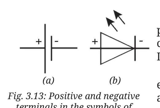
terminals in the symbols of
(a) a cell (b) an LED
Activity 3.10: Let us draw
• Using symbols shown in Table 3.2, draw the circuit diagram
of an electrical circuit given in Fig. 3.12a and Fig. 3.10c.
Are your circuit diagrams similar to Fig. 3.14a and Fig. 3.14b respectively?
(a)(b)
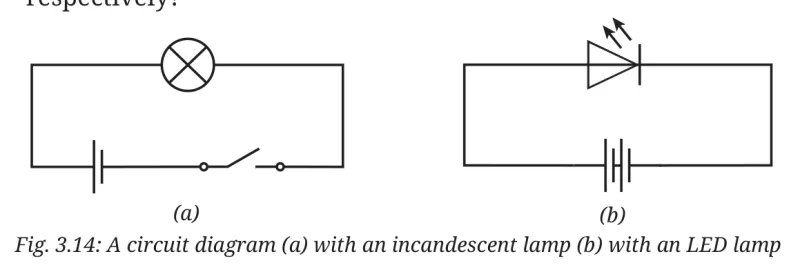
DIVEEEPER
International organisations, such as the International Electrotechnical Commission (IEC), American National Standards Institute (ANSI), and the Institute of Electrical and Electronics Engineers (IEEE) create standard symbols for electrical and electronic parts. Using the same symbols across the world helps people from different countries and industries understand each other easily.
3.4 Electrical Conductors and Insulators
Why did we use metal wires for making electric circuits? Can we not use some other materials for wires?
Also, why are electric wires covered with plastic or rubber?
Suppose, we make wires of materials other than metal and use them for making the electrical circuit. Do you think the electric current will pass through those materials in such a circuit?
Activity 3.11: Let us identify
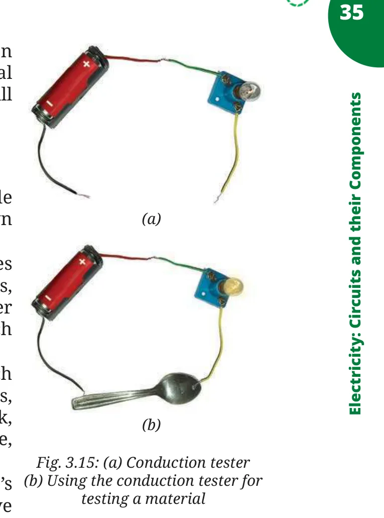
• Connect an electric cell and a lamp while leaving the two ends of wires free as shown in Fig. 3.15a. • Touch the two free ends of the wires momentarily. Does the lamp glow? If yes, our tester is ready. We can use this tester to identify the materials through which electric current passes. • Collect objects of diff erent materials, such as metal spoons, coins, cork, rubber, glass, keys, pins, plastic scale, wooden block, aluminium foil, candle, sewing needle, cardboard, paper, and pencil lead. • One by one, touch the free ends of the tester’s wires to both ends of each object you have collected (Fig. 3.15b). Make sure the wires don’t touch each other. Does the lamp glow every time? • Record your observations in Table 3.3.
(a)
(b)
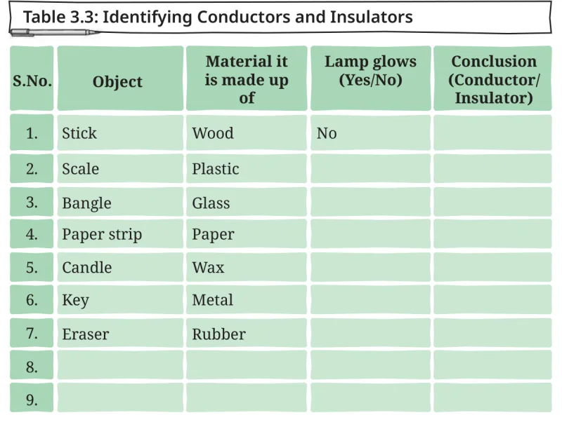
S.No.ObjectMaterial it is made up of
Lamp glows(Yes/No)Conclusion(Conductor/ Insulator)
StickWoodNo1.
2.
Scale
Plastic
3.
Bangle
Glass
4.
Paper stripPaper
5.
CandleWax
6.
Key
Metal
7.
Eraser
Rubber
8.
9.
• Analyse your observations. Did the lamp glow for all materials?The lamp glows for some materials only. This means that electric current can pass easily through some materials but not through others. The materials through which electric current can fl ow easily are called good conductors, or conductors of electricity. The materials through which current cannot pass through are called insulators, or poor conductors of electricity. • Based on the observations you have recorded in Table 3.3,
conclude which materials are conductors of electricity and which are insulators. Note it in Table 3.3.
From your conclusions in Table 3.3, you would have realised that metals are conductors of electricity, and thus, are used for making wires.
mak
DIVEEEPER
Silver, copper, and gold are the best electrical conductors. However, for making electrical wires, mainly copper is used due to its comparatively lower cost and abundant supply. Diff erent types of electrical wires are used for diff erent uses.
From Table 3.3, you would have also realised that plastic, rubber, and ceramics are electrical insulators. Have you now understood why wires are covered with those materials?Conductors and insulators are both important. Electrical wires, switches, connectors of plugs, and sockets are made of conductors. Insulators like rubber, plastics, and ceramics are used to cover wires, plug tops, and switches to protect people from electric shocks.
Caution — Our body is a conductor of electricity. Electric current passing through our body may cause severe injury or even death.Always handle electrical appliances with care. Never touch switches or plugs with wet hands, or use electrical devices in wet areas, or handle equipment with damaged insulation or broken plugs.
equ
DIVEEEPER
Have you ever wondered how the electricity from a cell or battery is diff erent from the electricity coming from a wall socket? Electricity from batteries usually powers small devices and is of a type called Direct Current (DC). In contrast, the electricity from power plants that come to the wall socket is known as Alternating Current (AC) and can run larger appliances.
In a Nutshell
nts
• An electric cell is a portable source of electrical energy. • An electric cell has two terminals; one is called positive (+ve) while the other is negative (–ve). • In an incandescent electric lamp, there is a thin wire called the fi lament, which gets hot and glows to produce light when electric current passes through it. • An LED has two terminals, one is positive (attached to a longer wire) and the other is negative (the shorter wire). • Electric current can pass through LED in one direction only. • An LED lights up only when its positive terminal (longer wire) connects to the positive terminal of the battery and its negative terminal (shorter wire) connects to the negative terminal of the battery. • A switch is a simple device that either completes or breaks a circuit. • The direction of electric current in a closed electrical circuit is taken to be from the positive to the negative terminal of the electric cell. • A representation of an electrical circuit using symbols is called its circuit diagram. • Materials through which electric current can fl ow easily are called good conductors or conductors of electricity. • Materials through which current cannot pass through are called insulators or poor conductors of electricity.
d their Componen
ENQUIRY